AI-generated mockup
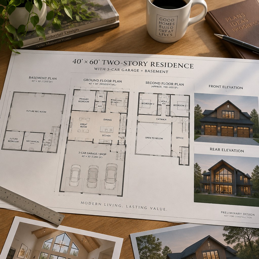
Absolutely. The original specification has good bones, but it was not actually dimensionally coherent. I’m going to preserve the intent—40’ × 60’ shell, full basement under the living portion, large garage, primary suite, vaulted great room, scullery, stacked stairs, two upstairs bedrooms + office/catwalk—and rebuild it around a single coordinate system. One important correction: this is a preliminary architectural programming/dimensioning document, not a stamped or code-certified plan. The architect/engineer still has to verify structure, egress, fire separation, stairs, HVAC, foundation, zoning, and the applicable Ohio code. PRELIMINARY FLOOR-PLAN SPECIFICATION 40’-0” × 60’-0” Two-Story Residence + Garage + 9’ Basement 1. Governing Geometry Overall building Exterior shell: 40’-0” wide × 60’-0” deep Coordinate system: * X = 0’-0” → west exterior wall * X = 40’-0” → east exterior wall * Y = 0’-0” → front exterior wall * Y = 60’-0” → rear exterior wall The building is divided along the Y axis: Zone Y dimension Area Garage / shop 30’-0” 1,200 SF Residential ground floor 30’-0” 1,200 SF Total shell 60’-0” 2,400 SF Fundamental arrangement 40'-0" 0' -------------------- 40' FRONT / DRIVEWAY Y=0' +-------------------------+ | | | GARAGE / SHOP | | | 30' Y=30' +-------------------------+ | | | RESIDENTIAL FLOOR | | | 30' Y=60' +-------------------------+ REAR / YARD This resolves the biggest ambiguity in the original plan: the garage occupies the entire front 40’ × 30’ portion and the house occupies the rear 40’ × 30’ portion. That gives you a very simple structural concept. ⸻ 2. Ground Floor — Residential Portion Residential footprint: 40’-0” × 30’-0” = 1,200 gross SF Rather than trying to force every room into the previous overlapping dimensions, I’m establishing three primary vertical zones: X-axis 0' 16' 32' 40' |---------------|--------------------|---------| Primary Great Room / Service / Suite Dining Stair Kitchen Core The exact interior partitions will be adjusted for wall thickness. Y-axis Y=30' REAR +----------------------------------------+ | PRIMARY | ENSUITE / WIC | | | | |--------------+-------------------------| | GREAT ROOM / DINING | KITCHEN | STAIRS | | | | | |---------------------+---------+---------| Y=0' FRONT However, because the garage occupies the front 30’, the residential floor actually begins at Y=30’. Therefore, for clarity, all residential dimensions below are measured from the residential front wall. ⸻ 3. Residential Ground-Floor Coordinate Grid For the residential portion: Residential Y=0’ = actual building Y=30’. Residential Y=30’ = actual building Y=60’. This allows the architect to work with a clean 40’ × 30’ rectangle. ⸻ 4. Primary Suite Primary bedroom Clear target: approximately 15’-0” × 14’-0” Location: * Southwest corner of residential floor * Exterior walls on west and rear sides * Two large rear windows * Additional west-side window if desired/appropriate Approximate coordinate envelope: X = 0’–15’-6” Y = 16’–30’ Target area: ~217.5 SF That’s plenty of room for: * King bed * Two nightstands * Dresser * Seating * Exterior windows * 3’-0” bedroom entry Bedroom door Target: 3’-0” × 6’-8” Positioned on the east/northeast side of the bedroom to create a direct relationship to the bathroom. ⸻ 5. Primary Bathroom + WIC Instead of pretending the entire 15’-6” × 14’ rectangle can simultaneously contain a bathroom AND an 8’6” closet without conflicts, divide the space intentionally. Primary bathroom Target: ~8’-0” × 10’-0” Features: * 7’-0” double vanity * 4’-0” × 5’-0” shower * 66” × 32” freestanding/soaker tub * Separate WC * Pocket door at WC * Linen storage Water closet Target: 3’-0” × 5’-0” minimum Use a pocket door. Walk-in closet Target: ~7’-6” × 8’-6” Features: * Two-sided hanging * Center circulation * Shoe/storage wall * Optional direct connection toward laundry Critical design change The WIC should be positioned so that it buffers the bedroom from the bathroom/service spaces, as originally intended. ⸻ 6. Great Room This is where I’d protect the design rather than sacrifice it to make the numbers work. Target clear dimensions ~22’-0” × 15’-0” Approximately: 330 SF The room should be the dominant architectural space. Features * Vaulted ceiling * Open-to-second-floor catwalk * Large rear glazing * 12’ × 8’ sliding/stacking door * Fireplace on interior wall * Dining zone adjacent to kitchen * Sightline from kitchen → fireplace → rear yard Important The 12’ opening should not automatically mean a 12’ structural opening. The structural engineer needs to design the header/beam and determine whether posts are required. ⸻ 7. Kitchen Target envelope Approximately: 12’-0” × 12’-0” to 13’-0” This is more realistic than trying to cram a 12’ × 14’-6” kitchen into the remaining space while simultaneously preserving the other rooms. Island 4’-0” × 8’-0” Potentially: 4’-0” × 8’-6” depending on final cabinetry. Island seating 12” overhang toward great room. Target: 4 seats Circulation Target: 42” working aisles Potentially: 48” behind seating where the circulation path crosses the island. Appliance arrangement Recommended conceptual sequence: Refrigerator → prep zone → sink → dishwasher → range → landing/prep The scullery should support the kitchen rather than become a second kitchen. ⸻ 8. Scullery / Pantry Target 6’-0” × 8’-0” Approximately: 48 SF Features: * Prep sink * Beverage refrigerator * Countertop * Floor-to-ceiling shelving * Small appliance storage * Bulk food storage * Optional secondary refrigerator/freezer Door Use either: * 2’-8” pocket door, or * concealed cabinet-style door But the concealed door should not compromise required wall/door clearances. ⸻ 9. Stair Core This is one area where the original specification needs a major correction. Target stair width 3’-6” clear minimum target I would actually design around: 3’-8”–4’-0” overall stair width if the architecture permits. Stair configuration Use a U-shaped or switchback stair, rather than trying to force a straight 14’-6” stair. Conceptually: UP +------+ | | | | +------+ || LANDING || +------+ | | | | +------+ DOWN This makes the 9’ floor-to-floor height much easier to accommodate. Preliminary stair target Assume approximately: 14’-0”–16’-0” total stair core length with final riser count determined from actual floor-to-floor elevation. Do not lock the 7-3/4” riser / 10” tread numbers until the architect establishes the actual floor-to-floor height. ⸻ 10. Entry / Drop Zone Because the garage is on the opposite side of the building from the residential floor in this revised configuration, the original “garage entry directly into the house hallway” needs reconsideration. There are two viable approaches. Option A — Internal garage connection Create a protected connection from garage → stair/service core → residential floor. Option B — Side/rear garage connection Better if the site permits: Garage → exterior covered passage/side entry → residential mudroom. I prefer Option B if the site allows it, because it keeps the house’s primary architectural entrance and great-room experience clean. ⸻ 11. Ground-Floor Bathroom Powder room Target: 4’-0” × 6’-0” Approximately: 24 SF Contents: * Toilet * 24–30” vanity * Mirror * Exhaust * Pocket or outswing door depending on final clearances ⸻ 12. Second Floor The second floor does not need to cover the entire 40’ × 30’ footprint. Target: ~700–850 SF enclosed/conditioned area with the remainder occupied by: * Open-to-below great room * Catwalk * Stair * mechanical/attic areas ⸻ 13. Bedroom 2 Target: 13’-0” × 11’-0” Approximately: 143 SF Features: * Reach-in closet * Rear exterior window * Code-compliant emergency escape/rescue opening * Standard bedroom door ⸻ 14. Bedroom 3 Target: 13’-0” × 11’-0” Approximately: 143 SF Mirror Bedroom 2. This creates a very efficient symmetrical rear bedroom arrangement. ⸻ 15. Jack-and-Jill Bathroom Target: 8’-0” × 7’-0” approximately Could be expanded slightly if necessary. Arrangement Bedroom 2 → vanity/vestibule → bathroom → vanity/vestibule → Bedroom 3 Or: BED 2 | VANITY | TUB/WC | VANITY | BED 3 Fixtures * 60” tub/shower * Two sinks * Toilet * Linen storage The exact plumbing arrangement should be coordinated vertically with the first-floor/basement plumbing. ⸻ 16. Upstairs Office Target: 11’-0” × 12’-0” Approximately: 132 SF Features: * Exterior window * 2’-8” door * Built-in desk option * Built-in storage * Future closet location Future Bedroom 4 Reserve wall space for: ~2’ deep × 6’ wide closet That makes the room much more easily convertible to a legal bedroom if desired, subject to the final code/egress configuration. ⸻ 17. Catwalk Target clear width 4’-0” This is a good dimension. It connects: Bedroom wing ↔ office/stair while overlooking the great room. Guard Final guard height and opening limitations must be confirmed under the applicable code. Architectural intent: * substantial wood/metal railing * open sightline * aligned with great-room windows * no unnecessary visual bulk ⸻ 18. Open-to-Below Target: ~22’ × 12’ This is one of the major architectural features. It creates: * two-story great-room volume * upper catwalk * large vertical fireplace wall * dramatic rear glazing * connection between floors But the structural framing around the opening needs to be designed from the beginning. ⸻ 19. Garage Now we get to the major improvement over the original document. Garage footprint 40’-0” × 30’-0” = 1,200 SF That’s enormous compared with a typical residential garage. It could accommodate: * 3-car garage * workshop * storage * mechanical/service area * trailer/toy storage Recommended conceptual division 40' +----------------------------------------+ | | | 3-CAR / LARGE VEHICLE BAY | | | | | |----------------------+-----------------| | WORKSHOP / STORAGE | UTILITY/STORAGE | | | | +----------------------+-----------------+ 30' For your long-term goals, I’d reserve at least 10’–12’ of the garage depth for workshop/storage, rather than simply making it an oversized three-car garage. ⸻ 20. Garage Door Configuration Possible arrangement: Three-car * 18’ × 8’ double door * 9’ × 8’ single door OR: Four-car / toy-oriented * 18’ × 8’ * 18’ × 8’ depending on site access and structural preference. Because you’re talking about a custom home rather than squeezing into a suburban lot, I’d design the structure around future vehicle/toy flexibility, not merely today’s cars. ⸻ 21. Basement Footprint 40’ × 30’ Target clear height 9’-0” This is a strong choice for future finishing. Foundation Conceptually: * poured concrete foundation * exterior waterproofing * perimeter drainage * sump system * radon provisions * structural reinforcement per engineer Don’t specify 8” vs. 10” concrete walls until the structural engineer and soil/site conditions are known. ⸻ 22. Basement Structural Concept Instead of specifying a beam size now, establish the structural intent: Primary beam Run approximately along the building’s centerline: X ≈ 20’-0” This divides the 40’ width into approximately: 20’ + 20’ The engineer can then determine whether the floor system can span those distances or whether another configuration is preferable. Columns Conceptually: * approximately 2–3 interior support points * aligned with architectural walls where possible * avoid placing columns in future recreation spaces This is much better than arbitrarily calling for a W8×24 before the loads are known. ⸻ 23. Basement Mechanical Zone Reserve approximately: 10’ × 12’ for: * water heater * HVAC * electrical * plumbing * sump * water softener * pressure tank if applicable * radon equipment * network/security equipment * future utility equipment Important Leave enough clearance around equipment for actual service access. Don’t design the mechanical room around the equipment’s footprint alone. ⸻ 24. Basement Future Layout Because you’re planning a growing family, I’d deliberately avoid putting permanent structural walls throughout the basement. Conceptual future zones: +----------------------------------------+ | | | FUTURE REC / FAMILY ROOM | | | | | |-------------------+--------------------| | FUTURE BEDROOM | FUTURE BATH / | | / GUEST SPACE | STORAGE | | | | +-------------------+--------------------+ The exact partitions can wait. ⸻ 25. Vertical Plumbing Alignment This is one of the smartest parts of your original concept, and I’d retain it. Create a primary plumbing spine approximately through the service side of the house. Align: Second-floor bathroom ↓ First-floor primary bathroom/powder ↓ Basement mechanical/plumbing zone That minimizes: * pipe runs * horizontal offsets * penetrations * labor * future maintenance ⸻ 26. Structural Grid For preliminary drafting, establish: Primary exterior grid A = west wall B = east wall 1 = front wall 2 = residential/garage dividing line 3 = rear wall Therefore: A B |-------------| 1 | GARAGE | | | 2 |-------------| | RESIDENTIAL | 3 |-------------| Then establish interior structural lines as needed. The key is that every wall gets a coordinate relative to this grid rather than every room being independently dimensioned. That prevents the exact problem in the original document. ⸻ 27. Final Preliminary Area Schedule Space Approx. Target Residential ground floor 1,200 SF gross Garage/shop 1,200 SF Basement 1,200 SF Primary bedroom ~218 SF Primary bath ~80 SF Primary WIC ~64 SF Great room/dining ~330 SF Kitchen ~150 SF Scullery ~48 SF Powder ~24 SF Bedroom 2 ~143 SF Bedroom 3 ~143 SF Jack & Jill ~56 SF Office ~132 SF Catwalk ~40–60 SF Open-to-below ~250+ SF The remainder is consumed by: * walls * circulation * stair * closets * mechanical/service spaces * structural requirements. ⸻ 28. What I Would Change From Your Original Specification Keep ✓ 40’ × 60’ overall concept ✓ 40’ × 30’ residential footprint ✓ 40’ × 30’ garage ✓ 9’ basement ✓ vaulted great room ✓ open catwalk ✓ primary suite ✓ large WIC ✓ scullery ✓ two upstairs bedrooms ✓ Jack-and-Jill ✓ upstairs office ✓ future bedroom conversion ✓ stacked plumbing ✓ basement mechanical zone Change ✗ Don’t call the original dimensions code-verified. ✗ Don’t specify a beam size yet. ✗ Don’t lock the stair rise/run yet. ✗ Don’t claim egress compliance yet. ✗ Don’t force the original 23’ + 6’-6” + 3’-6” horizontal dimensions—they don’t fit cleanly. ✗ Don’t treat independently specified room rectangles as proof that the plan fits. ✗ Don’t let the garage consume the architectural logic of the residence. ⸻ 29. The Next Level: Actual Coordinate Plan If I were handing this to a Revit drafter, I would take it one step further. The next document should look like this: 40'-0" A-------------------------B | | | GARAGE | | | | | |-------------------------| ← GRID 2 | | | PRIMARY | GREAT | | | SUITE | ROOM | KITCH | | | | | |---------|-------|-------| | | |STAIR | | | | | |---------|-------|-------| | | | REAR / YARD | +-------------------------+ 60' Then every single wall, door, window, stair, plumbing wall and structural support gets an X/Y coordinate. That is what turns this from a collection of good ideas into something a designer can actually reconstruct without guessing. And I’d go one step beyond that for your project: the next version should be a fully dimensioned “SD-101 / SD-102 / SD-103” style schematic package—ground floor, second floor, basement, exterior elevations, building section, door/window schedule, and a room-by-room area schedule. That would be the right bridge between your ideas and an actual architect/Revit model.
September 27, 2026
More ecommerce mockups